Work this month has been productive – and enlightening. I now know that the project’s original goals will be accomplished – changes in the planned corrective actions are made. The objectives of the project were to verify the previously described assumed causes of the two observed problem, and to determine and apply suitable corrective repairs. In the previous, in this, and in the following narratives, I have endeavored to not assign to the designer/builder any issues that might have arisen because of work done by the previous owner. Altamira’s previous owner has crossed the bar.
The first problem, stated as a question: Why do the cockpit hatch gutters not drain into the drain tubes provided at the transom and overboard, instead, always overflow water into the lazarette? The second: Why does rainwater always pool on the side decks at the rear of the aft cabin and in the cockpit, instead of flowing off and through the port and starboard relieving ports?
The missing bulkhead (actually the support it provided) was originally thought to be the source of both problems – now I know it was the source of only the second. The cockpit gutter drain problem exists because the boat was built with the defect.
This photo shows the transom (brighter white) to cockpit deck joint. From left to right is the transom sheer clamp, from foreground to background is one of four cockpit deck stringers (with factory installed nail). Note the white painted 3/4″ plywood block spacer between the two. Without these spacers, the stringers would hang in space when the deck mold is installed because the mold is too tall by about 3/4″. This insures that the rear of the hatches where the drains are (shown) is higher than the front – this insures that the drains do not work. One might ask “why not put the drains at the front of the gutters”? Not possible at build time because the front of the gutters is 18″ into the aft cabin (because of the cabin extension for the queen berth – previously discussed). The builder just glassed over the front part of the hatch opening and sloped that fiberglas panel so that the water that overflowed the gutter (all of it) just flowed aft down the slope into the lazarette and onto the rear surface of the plywood partition.
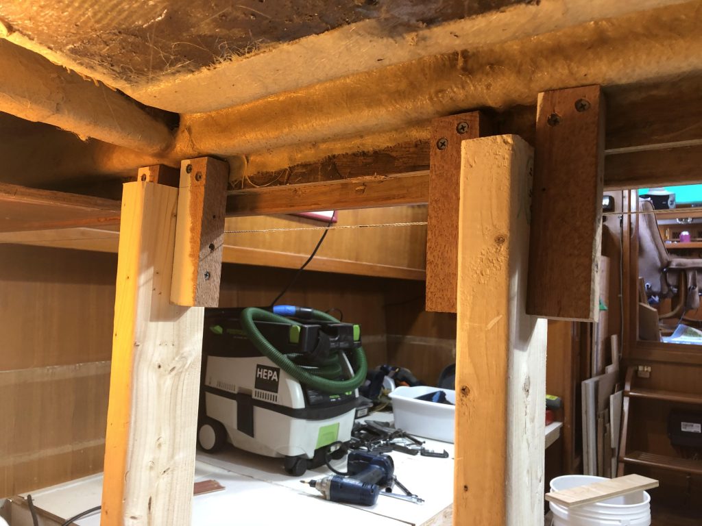
This photo shows the front of the hatch opening from below with the underside of the fiberglas water redirecting panel. The port front hatch gutter corner is above the panel, about at the left temporary support. To the left of the left temporary support, you can see the edge of the horizontal aft cabin interior plywood not yet removed. The new bulkhead panels will be installed just forward (to the photo background) of the permanent versions of these supports. Photo is looking forward – rough-in of port berth is shown.
So even though it is not possible to jack the cabin up enough to make the water drain correctly, I can install gutter drain tubes at the front of the gutters – because this lower location is now in the lazarette and not concealed in the cabin. Solution 33 years in the making.
I have jacked the cabin rear up enough to restore a crown to the cockpit at the cabin, water drains off to port and starboard as intended, and the cockpit is much firmer underfoot. The temporary supports (previous photo) hold up a port to starboard laminated beam the builder provided in the hope the original crown would not sag out. It proved inadequate, but will work fine supported six places across the beam with the permanent supports. The companionway opening (photo immediately below) also significantly weakened the cabin rear assembly.
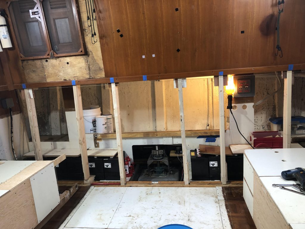
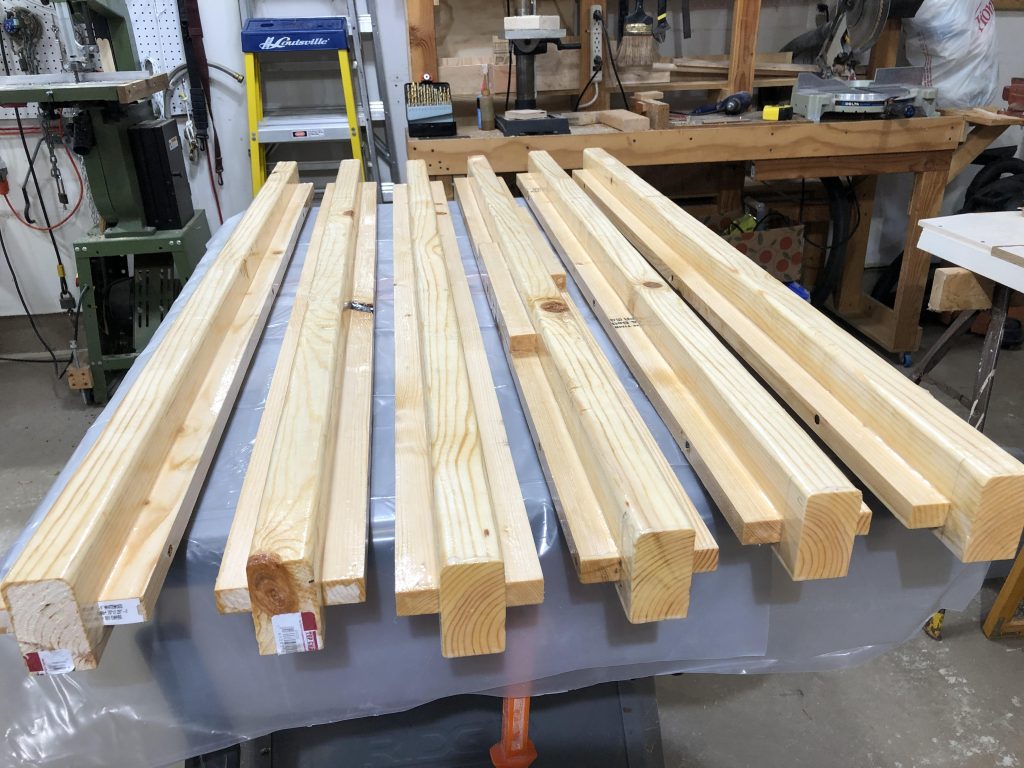
The first photo above shows the jacking/temporary supports in place (atop the new laminated floor beam) and the rough-in port and starboard berths, water tanks/piping below the berths – worked out OK. Most of the cabinetry removed will be re-installed across the aft cabin at the new rear bulkhead as a wide cabinet with cupboards above – the nice teak cabinet fronts and the strip heater will be retained, and the cabin lighting will be updated. The second photo shows the fabricated/laminated/epoxy coated permanent supports with cleats for the new panels ready for installation.